
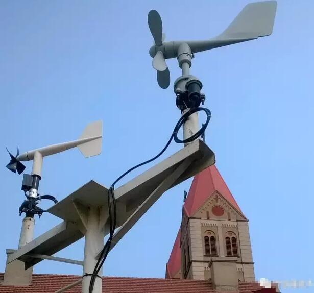
How to measure wind speed and wind direction, as a device for measuring weather, the wind speed sensor and wind direction sensor used to measure the direction of wind are also widely used in various industries. Let us look at these two devices. .
The wind direction sensor detects and senses the wind direction information of the wind by the rotation of the wind direction arrow, and transmits it to the coaxial code wheel, and simultaneously outputs a physical device corresponding to the wind direction related value.

Usually, the body of the wind direction sensor adopts the mechanical structure of the wind vane. When the wind blows to the tail of the tail of the wind vane, the arrow of the wind vane refers to the direction in which the wind blows. In order to maintain sensitivity to the direction, different internal mechanisms are utilized to discern the direction of the wind speed sensor. There are usually three categories:
Electromagnetic wind direction sensor: It is designed by the electromagnetic principle. Due to the variety of principles, the structure is very different. At present, some of these sensors have begun to use the gyro chip or electronic compass as the basic component, and the measurement accuracy has been further improved.
Photoelectric Wind Direction Sensor: This wind direction sensor uses an absolute Gray code disc as the basic component, and uses a special customized coding code to accurately output the corresponding wind direction information based on the photoelectric signal conversion principle.
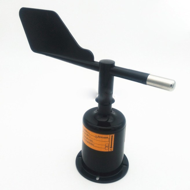
Resistive wind direction sensor: This wind direction sensor adopts a structure similar to a sliding varistor, and the maximum and minimum values of the generated resistance values are respectively marked as 360° and 0°. When the wind vane rotates, the sliding rod of the sliding varistor will follow The top of the wind vane rotates together, and the resulting voltage changes can calculate the angle or direction of the wind direction.
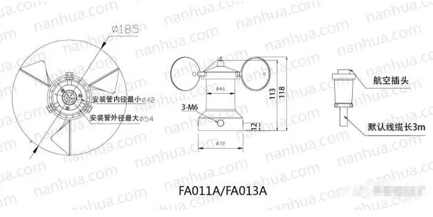
The wind speed sensor is a generic sensor that continuously measures wind speed and air volume (air volume = wind speed x cross-sectional area). The wind speed sensor is roughly classified into a mechanical type (mainly a propeller type, a cup type) wind speed sensor, a hot air type wind speed sensor, a pitot tube wind speed sensor, and an ultrasonic wind speed sensor based on an acoustic principle.
Propeller type wind speed sensor works
We are aware that the fan drives the fan blades to rotate by the motor, creating a pressure difference between the blades to push the airflow. The propeller anemometer work in the opposite direction. The blade system that aligns with the airflow is subject to wind pressure, which produces a certain torsional moment to rotate the blade system. Usually the propeller-type speed sensor measures the wind speed by rotating a set of three- or four-bladed propellers around a horizontal axis. The propeller is generally mounted on the front of a weathervane so that its plane of rotation is always facing the direction of the wind. Its speed depends on the wind speed. .
Wind cup type wind speed sensor works

The wind cup type wind speed sensor is a very common wind speed sensor originally invented by British Rubinson. The sensing portion consists of three or four conical or hemispherical empty cups. Hollow cup shells are fixed on a trigeminal star bracket that is 120° apart or a 90° cross-shaped bracket. The concave surfaces of the cups are classified in one direction, and the entire cross arm frame is fixed on a vertical rotating shaft.
When the wind blows from the left, the wind cup 1 is parallel to the wind direction, and the force of the wind against the cup 1 is approximately zero in the direction closest to the axis of the cup. The wind cup 2 and 3 intersect with the wind direction at an angle of 60 degrees. the wind cup 2, the concave surface faces the wind and the wind pressure is the greatest; the wind cup 3 has its convex surface facing the wind, and the wind flows around it to make it subject to wind pressure. Smaller than the wind cup 2, due to the pressure difference between the cup 2 and the cup 3 in the direction perpendicular to the cup axis, the cup starts to rotate clockwise, and the wind speed is larger, the initial pressure difference is larger, resulting in The greater the acceleration, the faster the cup rotates.
After the wind cup starts to rotate, since the cup 2 rotates in the direction of the wind, the pressure of the wind is relatively reduced, and the cup 3 rotates at the same speed against the wind, the wind pressure is relatively increased, and the wind pressure difference is continuously reduced. After a period of time (when the wind speed is stable), when the partial pressure difference acting on the three wind cups is zero, the wind cup becomes a uniform rotation. In this way, the wind speed can be established according to the rotational speed of the cup (the number of turns per second).
When the wind cup rotates, the coaxial multi-toothed optical disc or the magnetic rod is driven to rotate, and a pulse signal proportional to the rotational speed of the wind cup is obtained through the circuit, and the pulse signal is counted by the counter, and the actual wind speed value can be obtained after being converted. At present, the new rotor anemometers are three cups, and the performance of the code is better than that of the hemisphere. When the wind speed increases, the rotor can increase the speed quickly to adapt to the airflow speed. When the wind speed decreases, the speed is influenced by inertia. However, it cannot be immediately lowered. The wind speed indicated by the rotary anemometer in the formation wind is generally too high to become an excessive effect (the average error generated is about 10%).
Thermal wind speed sensor works
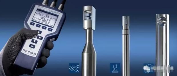
The thermal wind speed sensor uses a hot wire (tungsten or platinum wire) or a hot film (a film made of platinum or chrome) as a probe, exposed to the air to be measured, and connected to the Wheatstone bridge through Whist The balance of the resistance or current of the bridge is used to detect the flow rate of the air to be measured. The hot film type wind speed sensor is coated with a very thin quartz film insulating layer to insulate it from the fluid and prevent contamination. It can work in a gas stream with particles, and its strength is higher than that of the metal heated wire.
When the air temperature is stable, the power consumption on the hot wire is equal to the heat that the burning wire instantaneously consumes in the air. The wire resistance changes with temperature, and the resistance of the hot wire and the hot wire temperature is in a linear relationship within the normal temperature range (0 to 300 °C). The heat release coefficient is related to the air flow speed. The larger the flow rate, the larger the corresponding heat release coefficient, that is, the heat dissipation is fast; the flow rate is small, and the heat dissipation is slow.
The airflow velocity measured by the thermal wind speed sensor is dependent upon current and resistance. Keep the contemporary (or resistance) constant, and the measured airflow speed is only one-to-one with the resistance (or current).
The hot wire type winds speed sensor has two design circuits of constant current and constant temperature. Constant temperature hot wire wind speed sensors are more commonly used. The principle of constant temperature method is to keep the temperature of the heated wire constant during the measurement process, so that the bridge is balanced. At this time, the resistance of the heated wire remains unchanged. Air flow speed is only a single value function of the current. According to the known relationship between the air flow speed and the current, the current can be generated. The airflow velocity of the end device. The persistent current hot wire wind speed sensor keeps the current value flowing through the hot wire unchanged during the measurement. When the current value is invariable, the gas flow rate is only related to the wire resistance. The airflow velocity through the wind speed sensor can be identified based on the known relationship between the airflow velocity and the wire resistance.

The hot wire wind speed sensor measures the pulsating wind speed. The constant current type wind speed sensor has large thermal inertia, and the relentless temperature type wind speed sensor has relatively small thermal inertia and high speed response. The measurement accuracy of the hot wire type wind speed sensor is not very lofty, so pay attention to temperature compensation when using.
Pitot tube wind speed sensor works

Pitot tube, also known as “airspeed tube”, “wind speed tube”, is a tubular device for measuring the total pressure of airflow and static pressure to determine the speed of airflow. It is named after the invention of French H. Pito.
It is therefore difficult to directly measure the velocity of the gas stream by experimental methods, but the pressure of the gas stream can be conveniently measured with a manometer. It is mainly used to measure the speed of the aircraft. But also has many other functions. Therefore, the pressure can be measured by the pitot tube, and then the Bernoulli’s theorem can be utilized to calculate the velocity of the airflow. The pitot tube consists of a double-headed casing (see picture). The outer casing has a diameter D. At the center O of the rounded head, a total pressure hole is connected to the inner casing, and one end of the pressure gauge is connected. The diameter is 0.3 to 0.6D.
A row of static pressure holes perpendicular to the outer tube wall is uniformly opened in the circumferential direction at a side of the outer sleeve side surface at a distance of about 3 to 8 D, and the other end of the pressure gauge is connected to place the pitot tube at a constant flow rate to be measured. In the middle, the tube axis is aligned with the direction of the airflow, and the leading edge of the tube is opposite to the flow. When the airflow approaches the O point, its flow rate gradually decreases, and the flow to the O point stagnate to zero. Therefore, the total pressure P is measured at point O. Secondly, since the tube is very thin, the point C is sufficiently far from the point O, so the speed and pressure at the point C have substantially recovered to the same value as the flow velocity V and the pressure P, so that the static pressure is measured at the point C. . For low-speed flow (fluids can be considered to be incompressible), the formula for determining the flow rate by Bernoulli’s theorem is:

According to the total pressure and static pressure difference P-P measured by the pressure gauge, and the density ρ of the fluid, the velocity of the airflow can be obtained according to the equation (1).
Ultrasonic wind speed sensor works

The working principle of the ultrasonic wind speed sensor is to use the ultrasonic time different method to measure the wind speed. Due to the speed at which sound travels in the air, it is superimposed on the velocity of the airflow in the wind. If the direction of propagation of the ultrasonic wave is the same as the direction of the wind, then its speed will increase; conversely, if the direction of propagation of the ultrasonic wave is opposite to the direction of the wind, its speed will be slower.
Therefore, under fixed detection conditions, the speed at which ultrasonic waves propagate in the air can correspond to the wind speed function. Accurate wind speed and direction can be achieved by calculation. Since sound waves propagate in the air, its velocity is considerably affected by temperature; the wind speed sensor detects two opposite directions on the two channels, so the effect of temperature on the speed of sound waves is negligible.
The ultrasonic wind speed sensor is lightweight, has no moving parts, is rugged, and requires no maintenance and field calibration to simultaneously output wind speed and direction. Customers can choose the wind speed unit, output frequency and output format as needed. It is possible to select a heating device (recommended in an ice-cold environment) or an analog output as needed. Can be accompanied by computers, data collectors or other acquisition devices that have RS485 or analog output. If necessary, multiple networks can be invoked as one.

Ultrasonic wind speed and direction instrument is a more advanced instrument for measuring wind speed and direction. Because it overcomes the inherent defects of the mechanical wind speed and direction instrument, it can work normally all the time and for a long time, and is utilized more and more widely. It will be a compelling alternative to mechanical anemometers.
Ultrasonic wind speed sensor features:
1. Acoustic phase compensation technology is adopted, and the precision is higher;
2, using random error recognition technology, can also ensure low dispersion error of measurement under high wind, so that the output is more stable;
3. For the measurement and compensation technology of drizzle and dense fog weather, it has stronger environmental adaptability;
4, digital filtering technology, anti-electromagnetic interference ability is stronger;
5, no start wind speed limit, zero wind speed work, suitable for indoor breeze measurement, no angle limit (360 ° all-round), while obtaining wind speed, wind direction data;
6, high measurement accuracy; stable performance; low power consumption does not require calibration;
7. The structure is firm. The instrument is highly resistant to corrosion, and there is no need to worry about damage during installation and use;
8. Flexible design, lightweight, light carrying, easy to install and disassemble;
9, the signal access is convenient, and both digital and analog signals are provided;
10, no maintenance and on-site calibration, true 0 ~ 359 work (no dead angle).
