Anemometer, also known as anemometer, is an instrument for measuring air flow rate. It can be widely used in various fields, such as electric power, steel, petrochemical, energy conservation, etc. In daily life, many industries need to use anemometers, such as fan manufacturing. Wind, wind and air volume measurements are required to ensure normal operation.
First, anemometer use precautions
1. Do not expose the probe and the anemometer body to the rain. Otherwise, there may be electric shock, fire and personal injury.
2. Do not touch the sensor part of the probe while the anemometer is energized. Otherwise, it will affect the measurement results or cause damage to the internal circuit of the anemometer.
3. When the anemometer is not used for a long time, remove the internal battery. Otherwise, the battery may leak and the anemometer may be damaged.
4. Do not wipe the anemometer with volatile liquids. Otherwise, it may cause deformation and discoloration of the anemometer housing. When there is stain on the surface of the anemometer, use a soft fabric and a neutral detergent to wipe.
5. Do not place the anemometer in a place subject to high temperatures, high humidity, excessive dust and direct sunlight. Failure to do so may result in damage to internal components or deterioration of anemometer performance.
6. Do not drop or press the anemometer. Failure to do so will result in malfunction or damage to the anemometer.
7. It is forbidden to use an anemometer in a flammable gas environment.
8. Please use the anemometer correctly according to the requirements of the instruction manual. Improper use can result in electric shock, fire, and damage to the sensor.
9. In use, if the anemometer emits an unusual smell, sound or smoke, or if liquid flows into the anemometer, shut down the battery immediately. Otherwise, there is a danger of electric shock, fire and damage to the anemometer.
10. Do not disassemble or modify the anemometer. Failure to do so may result in electric shock or fire.
11. Do not touch the internal sensor part of the probe.
12. Do not place the anemometer probe in a flammable gas. Failure to do so may result in fire or even explosion.
Second, the classification of anemometer
According to the principle: thermal anemometer, ultrasonic anemometer, impeller anemometer, three-cup anemometer, windmill anemometer, pitot tube anemometer, etc.
According to the shape of the probe: there is a pointing anemometer, a non-directional anemometer
According to the test range and test parameters: medium and high temperature anemometer, micro wind speed meter, multi-parameter environmental test meter, etc.
Third, anemometer product application field
It can measure wind speed and air temperature. This anemometer can be used in indoor air quality/industrial health environment, environmental testing in pipelines, performance tuning of HVAC equipment, etc.
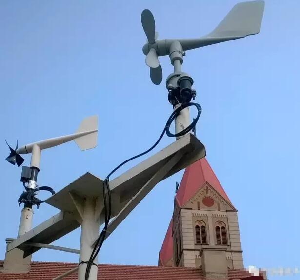
The hand-held wind speed and direction meter is developed by Zhejiang Top Yunnong Technology Co., Ltd., which can be used for monitoring wind speed and wind speed in meteorological monitoring, agricultural and forestry crop planting, navigation and aviation. The instrument consists of poles, wind vanes and wind cups. And wind direction wind speed sensor.
The wind cup can measure the direction of the wind, while the speed of the cup can be used for wind speed calculation. The instrument can be charged, with charging protection and low voltage prompt function. It can manually record the wind direction wind speed. It can also be automatically monitored by the instrument for a long time. The instrument has a voice alarm function and can broadcast over-limit information. The monitoring data can be transmitted wirelessly, and the user can view the monitoring data on the webpage.
The installation direction of the handheld wind speed and direction indicator should be directed to the north direction. If the pointing is deviated, a one-key clear operation is required. After facing the north direction, press and hold the operation button for 1-2 seconds to automatically clear. Avoid high temperature, high humidity, dusty, direct sunlight, and avoid affecting the performance of the instrument.
The instrument uses a low-power design, increases system monitoring and protection measures, and can work long hours to avoid system crashes. The instrument host has a large storage capacity and can record multiple sets of data. The instrument has a built-in lithium battery function.
The hand-held wind speed and direction indicator is a more sophisticated instrument that is resistant to shock and vibration and should not be used in places with excessive dust or corrosiveness.
There are 4 batteries in the instrument, which are divided into two groups. One group is three-section series, one group is single-section. When adjusting the “full-scale adjustment” knob, if the meter can not reach full scale, it means that the single-cell battery has been exhausted. When adjusting the “coarse adjustment” and “fine adjustment” knobs, if the meter pointer cannot return to zero point, it means that the three batteries have been exhausted. When replacing the battery, open the small door at the bottom of the instrument and connect it in the correct direction. After the instrument is repaired, it must be recalibrated.
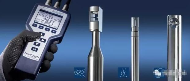
working principle:
A speed measuring instrument that converts a flow rate signal into an electrical signal that also measures fluid temperature or density. The principle is that a thin wire (called) electrically heated is placed in the airflow, and the amount of heat dissipation in the airflow is related to the flow rate, and the heat dissipation causes a temperature change to cause a resistance change, and the flow rate signal is converted into an electrical signal. It has two working modes: 1 constant current. The passing current remains unchanged. When the temperature changes, the resistance changes, so the voltage at both ends changes, thereby measuring the flow rate; 2 constant temperature type. The temperature remains the same, such as maintaining 150 ° C, the flow rate can be measured according to the current applied. The thermostatic type is more widely used than the constant current type.
The length is generally in the range of 0.5 to 2 mm, and the diameter is in the range of 1 to 10 μm. The material is platinum, tungsten or platinum-rhodium alloy. If a thin metal film (thickness less than 0.1 micron) is used instead of the metal wire, it is a hot film anemometer, which functions similarly to the hot wire, but is mostly used to measure the liquid flow rate. In addition to the ordinary single line type, it can also be a combined two-wire or three-wire type to measure the velocity component in all directions. The output electrical signal is amplified, compensated and digitized and input into the computer to improve the measurement accuracy, automatically complete the data post-processing process, and expand the speed measurement function, such as simultaneously completing the instantaneous value and the time average value, the combined speed and the sub-speed, the turbulence and Measurement of other turbulence parameters. Compared with the pitot tube, the anemometer [1] has a small probe volume, small interference to the flow field, fast response, and can measure unsteady flow rate; it can measure very low speed (such as as low as 0.3 m/s).
When a thermal probe is used in turbulent flow, airflow from all directions simultaneously impacts the thermal element, which can affect the accuracy of the measurement. When measured in turbulent flow, the temperature indicator of the thermal anemometer is often higher than that of the rotary probe. The above phenomenon can be observed during the pipeline measurement process. Depending on the design of the management pipe turbulence, it can occur even at low speeds. Therefore, the anemometer measurement process should be performed in the straight section of the pipe. The starting point of the straight line should be at least 10 × D (D = pipe diameter, in CM) before the measuring point; the end point is at least 4 × D behind the measuring point. The fluid section must not have any obstructions (angles, rehangs, objects, etc.).
product instructions:
1. Before using, observe whether the pointer of the meter refers to the zero point. If there is an offset, gently adjust the mechanical adjustment screw of the meter to return the pointer to zero point;
2. Put the correction switch in the off position
3. Insert the measuring rod plug into the socket, the measuring rod is placed vertically upwards, the screw plug is pressed tightly to seal the probe, the “correction switch” is placed at the full position, and the “full adjustment” knob is slowly adjusted to make the meter pointer full. Degree position
4. Set the “correction switch” to “zero position” and slowly adjust the “coarse adjustment” and “fine adjustment” two knobs so that the meter pointer points to the zero position.
5. After the above steps, gently pull the screw plug to expose the probe (the length can be selected according to the need), and make the red dot on the probe face the wind direction. According to the meter reading, check the calibration curve to find out. Measured wind speed;
6. After measuring a few points (about 10 minutes), the above steps 3 and 4 must be repeated to standardize the current in the meter. After the test, the “correction switch” should be placed in the off position.
How to measure wind speed and wind direction, as a device for measuring weather, the wind speed sensor and wind direction sensor used to measure the direction of wind are also widely used in various industries. Let us look at these two devices. .
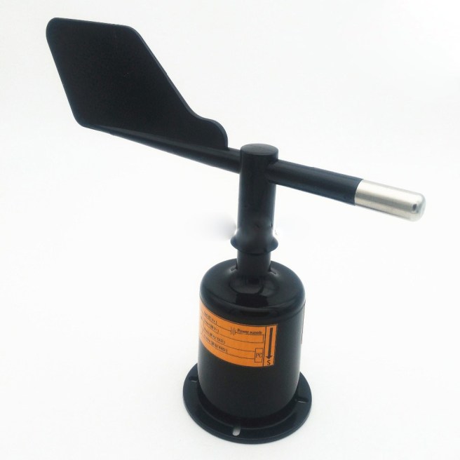
The wind direction sensor detects and senses the wind direction information of the wind by the rotation of the wind direction arrow, and transmits it to the coaxial code wheel, and simultaneously outputs a physical device corresponding to the wind direction related value.
Usually, the body of the wind direction sensor adopts the mechanical structure of the wind vane. When the wind blows to the tail of the tail of the wind vane, the arrow of the wind vane refers to the direction in which the wind blows. In order to maintain sensitivity to the direction, different internal mechanisms are utilized to discern the direction of the wind speed sensor. There are usually three categories:
Electromagnetic wind direction sensor: It is designed by the electromagnetic principle. Due to the variety of principles, the structure is very different. At present, some of these sensors have begun to use the gyro chip or electronic compass as the basic component, and the measurement accuracy has been further improved.
Photoelectric Wind Direction Sensor: This wind direction sensor uses an absolute Gray code disc as the basic component, and uses a special customized coding code to accurately output the corresponding wind direction information based on the photoelectric signal conversion principle.
Resistive wind direction sensor: This wind direction sensor adopts a structure similar to a sliding varistor, and the maximum and minimum values of the generated resistance values are respectively marked as 360° and 0°. When the wind vane rotates, the sliding rod of the sliding varistor will follow The top of the wind vane rotates together, and the resulting voltage changes can calculate the angle or direction of the wind direction.
The wind speed sensor is a generic sensor that continuously measures wind speed and air volume (air volume = wind speed x cross-sectional area). The wind speed sensor is roughly classified into a mechanical type (mainly a propeller type, a cup type) wind speed sensor, a hot air type wind speed sensor, a pitot tube wind speed sensor, and an ultrasonic wind speed sensor based on an acoustic principle.
Propeller type wind speed sensor works
We are aware that the fan drives the fan blades to rotate by the motor, creating a pressure difference between the blades to push the airflow. The propeller anemometer work in the opposite direction. The blade system that aligns with the airflow is subject to wind pressure, which produces a certain torsional moment to rotate the blade system. Usually the propeller-type speed sensor measures the wind speed by rotating a set of three- or four-bladed propellers around a horizontal axis. The propeller is generally mounted on the front of a weathervane so that its plane of rotation is always facing the direction of the wind. Its speed depends on the wind speed. .
Wind cup type wind speed sensor works
The wind cup type wind speed sensor is a very common wind speed sensor originally invented by British Rubinson. The sensing portion consists of three or four conical or hemispherical empty cups. Hollow cup shells are fixed on a trigeminal star bracket that is 120° apart or a 90° cross-shaped bracket. The concave surfaces of the cups are classified in one direction, and the entire cross arm frame is fixed on a vertical rotating shaft.
When the wind blows from the left, the wind cup 1 is parallel to the wind direction, and the force of the wind against the cup 1 is approximately zero in the direction closest to the axis of the cup. The wind cup 2 and 3 intersect with the wind direction at an angle of 60 degrees. the wind cup 2, the concave surface faces the wind and the wind pressure is the greatest; the wind cup 3 has its convex surface facing the wind, and the wind flows around it to make it subject to wind pressure. Smaller than the wind cup 2, due to the pressure difference between the cup 2 and the cup 3 in the direction perpendicular to the cup axis, the cup starts to rotate clockwise, and the wind speed is larger, the initial pressure difference is larger, resulting in The greater the acceleration, the faster the cup rotates.
After the wind cup starts to rotate, since the cup 2 rotates in the direction of the wind, the pressure of the wind is relatively reduced, and the cup 3 rotates at the same speed against the wind, the wind pressure is relatively increased, and the wind pressure difference is continuously reduced. After a period of time (when the wind speed is stable), when the partial pressure difference acting on the three wind cups is zero, the wind cup becomes a uniform rotation. In this way, the wind speed can be established according to the rotational speed of the cup (the number of turns per second).
When the wind cup rotates, the coaxial multi-toothed optical disc or the magnetic rod is driven to rotate, and a pulse signal proportional to the rotational speed of the wind cup is obtained through the circuit, and the pulse signal is counted by the counter, and the actual wind speed value can be obtained after being converted. At present, the new rotor anemometers are three cups, and the performance of the code is better than that of the hemisphere. When the wind speed increases, the rotor can increase the speed quickly to adapt to the airflow speed. When the wind speed decreases, the speed is influenced by inertia. However, it cannot be immediately lowered. The wind speed indicated by the rotary anemometer in the formation wind is generally too high to become an excessive effect (the average error generated is about 10%).
Thermal wind speed sensor works
The thermal wind speed sensor uses a hot wire (tungsten or platinum wire) or a hot film (a film made of platinum or chrome) as a probe, exposed to the air to be measured, and connected to the Wheatstone bridge through Whist The balance of the resistance or current of the bridge is used to detect the flow rate of the air to be measured. The hot film type wind speed sensor is coated with a very thin quartz film insulating layer to insulate it from the fluid and prevent contamination. It can work in a gas stream with particles, and its strength is higher than that of the metal heated wire.
When the air temperature is stable, the power consumption on the hot wire is equal to the heat that the burning wire instantaneously consumes in the air. The wire resistance changes with temperature, and the resistance of the hot wire and the hot wire temperature is in a linear relationship within the normal temperature range (0 to 300 °C). The heat release coefficient is related to the air flow speed. The larger the flow rate, the larger the corresponding heat release coefficient, that is, the heat dissipation is fast; the flow rate is small, and the heat dissipation is slow.
The airflow velocity measured by the thermal wind speed sensor is dependent upon current and resistance. Keep the contemporary (or resistance) constant, and the measured airflow speed is only one-to-one with the resistance (or current).
The hot wire type winds speed sensor has two design circuits of constant current and constant temperature. Constant temperature hot wire wind speed sensors are more commonly used. The principle of constant temperature method is to keep the temperature of the heated wire constant during the measurement process, so that the bridge is balanced. At this time, the resistance of the heated wire remains unchanged. Air flow speed is only a single value function of the current. According to the known relationship between the air flow speed and the current, the current can be generated. The airflow velocity of the end device. The persistent current hot wire wind speed sensor keeps the current value flowing through the hot wire unchanged during the measurement. When the current value is invariable, the gas flow rate is only related to the wire resistance. The airflow velocity through the wind speed sensor can be identified based on the known relationship between the airflow velocity and the wire resistance.
The hot wire wind speed sensor measures the pulsating wind speed. The constant current type wind speed sensor has large thermal inertia, and the relentless temperature type wind speed sensor has relatively small thermal inertia and high speed response. The measurement accuracy of the hot wire type wind speed sensor is not very lofty, so pay attention to temperature compensation when using.
Pitot tube wind speed sensor works
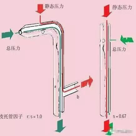
Pitot tube, also known as “airspeed tube”, “wind speed tube”, is a tubular device for measuring the total pressure of airflow and static pressure to determine the speed of airflow. It is named after the invention of French H. Pito.
It is therefore difficult to directly measure the velocity of the gas stream by experimental methods, but the pressure of the gas stream can be conveniently measured with a manometer. It is mainly used to measure the speed of the aircraft. But also has many other functions. Therefore, the pressure can be measured by the pitot tube, and then the Bernoulli’s theorem can be utilized to calculate the velocity of the airflow. The pitot tube consists of a double-headed casing (see picture). The outer casing has a diameter D. At the center O of the rounded head, a total pressure hole is connected to the inner casing, and one end of the pressure gauge is connected. The diameter is 0.3 to 0.6D.
A row of static pressure holes perpendicular to the outer tube wall is uniformly opened in the circumferential direction at a side of the outer sleeve side surface at a distance of about 3 to 8 D, and the other end of the pressure gauge is connected to place the pitot tube at a constant flow rate to be measured. In the middle, the tube axis is aligned with the direction of the airflow, and the leading edge of the tube is opposite to the flow. When the airflow approaches the O point, its flow rate gradually decreases, and the flow to the O point stagnate to zero. Therefore, the total pressure P is measured at point O. Secondly, since the tube is very thin, the point C is sufficiently far from the point O, so the speed and pressure at the point C have substantially recovered to the same value as the flow velocity V and the pressure P, so that the static pressure is measured at the point C. . For low-speed flow (fluids can be considered to be incompressible), the formula for determining the flow rate by Bernoulli’s theorem is:
According to the total pressure and static pressure difference P-P measured by the pressure gauge, and the density ρ of the fluid, the velocity of the airflow can be obtained according to the equation (1).
Ultrasonic wind speed sensor works
The working principle of the ultrasonic wind speed sensor is to use the ultrasonic time different method to measure the wind speed. Due to the speed at which sound travels in the air, it is superimposed on the velocity of the airflow in the wind. If the direction of propagation of the ultrasonic wave is the same as the direction of the wind, then its speed will increase; conversely, if the direction of propagation of the ultrasonic wave is opposite to the direction of the wind, its speed will be slower.
Therefore, under fixed detection conditions, the speed at which ultrasonic waves propagate in the air can correspond to the wind speed function. Accurate wind speed and direction can be achieved by calculation. Since sound waves propagate in the air, its velocity is considerably affected by temperature; the wind speed sensor detects two opposite directions on the two channels, so the effect of temperature on the speed of sound waves is negligible.
The ultrasonic wind speed sensor is lightweight, has no moving parts, is rugged, and requires no maintenance and field calibration to simultaneously output wind speed and direction. Customers can choose the wind speed unit, output frequency and output format as needed. It is possible to select a heating device (recommended in an ice-cold environment) or an analog output as needed. Can be accompanied by computers, data collectors or other acquisition devices that have RS485 or analog output. If necessary, multiple networks can be invoked as one.
Ultrasonic wind speed and direction instrument is a more advanced instrument for measuring wind speed and direction. Because it overcomes the inherent defects of the mechanical wind speed and direction instrument, it can work normally all the time and for a long time, and is utilized more and more widely. It will be a compelling alternative to mechanical anemometers.
Ultrasonic wind speed sensor features:
1. Acoustic phase compensation technology is adopted, and the precision is higher;
2, using random error recognition technology, can also ensure low dispersion error of measurement under high wind, so that the output is more stable;
3. For the measurement and compensation technology of drizzle and dense fog weather, it has stronger environmental adaptability;
4, digital filtering technology, anti-electromagnetic interference ability is stronger;
5, no start wind speed limit, zero wind speed work, suitable for indoor breeze measurement, no angle limit (360 ° all-round), while obtaining wind speed, wind direction data;
6, high measurement accuracy; stable performance; low power consumption does not require calibration;
7. The structure is firm. The instrument is highly resistant to corrosion, and there is no need to worry about damage during installation and use;
8. Flexible design, lightweight, light carrying, easy to install and disassemble;
9, the signal access is convenient, and both digital and analog signals are provided;
10, no maintenance and on-site calibration, true 0 ~ 359 work (no dead angle).
The purpose of the wind vane is to indicate the wind direction and provide a wind speed reference. Widely used in meteorology, chemical, mining, agriculture, oilfield exploration and other industries.
The wind vane is an instrument that measures the direction of the wind. It is usually installed on a pole that is about 10 meters high and is about to be separated from the ground. Under the action of wind pressure, the wind vane arrow refers to the direction of the wind. It is generally divided into three parts: the head, the horizontal pole and the tail.
Principle
When the direction of the wind is marked with the wind direction at an angle, the wind exerts pressure on the wind vane, which can be broken down into two winds that are parallel and perpendicular to the wind vane. Because the wind direction head is relatively small in wind area, the wind receiving area of The tail is relatively large, so the perceived wind pressure is not equal. The wind pressure perpendicular to the tail produces a wind pressure moment, so that the wind direction rotates around the vertical axis until the wind head is right against the wind. When the direction comes, the wind vane is stable in a certain position due to the balance of the two sides of the wing.
The arrow of the wind vane always points to the source of the wind. The principle is actually very simple: the area of The wind is larger than the arrow. If the arrow and the tail are both affected by the wind, the tail will be pushed by the wind, and the arrow will be moved to the source of the wind. The wind vane is placed on the high pole. In order to make the wind direction record more accurate, the wind direction must be measured with a compass at the bottom of the pole for 10 seconds (the wind direction must be stable at that time).
What is the output of the wind direction sensor? If you can integrate the output into 4-20ma current or 0-10v voltage, you can directly connect to the PLC to get the analog input port. According to the response curve, you can get the wind direction and speed
Adc value conversion voltage
Temperature (° C) = {(V25 – VSENSE)/Avg_Slope} + 25
Here:
V25 = VSENSE at 25 ° C
Avg_Slope = temperature and average VSENSE curve slope (unit for mV / ° C or mu V / ° C)
Refer to the actual values of V25 and Avg_Slope in the electrical characteristics section of the data manual.
Not same, but they are related. The wind volume is equal to the product of the wind speed and the cross-section of the inlet, so the wind volume sensor should be the wind speed sensor after conversion.
Sensor (English name: pinch /sensor) is a kind of detection device, which can feel the measured information and transform the information into
the electric signal or other required form of information output according to certain law, so as to satisfy the requirements of information transmission, processing, storage, display, record and control.
The characteristics of sensors include miniaturization, digitization, intelligence, multi-function, systematization and networking. It is the first step to realize automatic detection and control. With the existence and development of sensors, objects have senses of touch, taste and smell, and gradually become alive. Generally, according to its basic perception function, it can be divided into ten categories: thermal sensor, light sensor, gas sensor, force sensor, magnetic sensor, moisture sensor, sound sensor, radiation sensor, color sensor and taste sensor.
The common wind sensor, the internal is a 360 degrees variable resistance, so the output is a variable resistance. It can be easily converted to voltage output by applying an applied dc voltage.
As the name suggests, the wind direction and speed sensor is a tool to measuring wind direction and speed. It is a machine that converts the variable of air flow velocity into a corresponding output signal, and can be widely used in meteorological, military, aviation, harbor, environmental protection, industry, agriculture and forestry departments to measure horizontal wind parameters.
In these applications, wind direction and speed are of great importance parameters, so the wind direction anemometer has become a universal measuring tool. Wind direction anemometer contains two sensors, wind direction sensor and the wind speed sensor. The two sensors work simultaneously to measure both wind direction and speed.
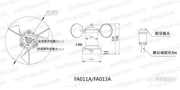
The sensor component of the wind speed sensor of the wind direction and wind speed monitor is a three-cup wind cup component, which generates rotation when the wind speed is greater than 0.4m/s, and the signal conversion circuit is all integrated circuit. The horizontal wind drives the downwind cup configure on rotate, and the magnetic rod is driven to rotate by the spindle. dozen of small magnets on it from a number of rotating magnetic fields, and the hall magnetic sensor induces pulse signals, whose frequency increases linearly with the increase of wind speed. Calculation formula:V= 0.1f; V: wind speed, unit:m/s; F: pulse frequency, unit:Hz.
The sensing component of the wind direction sensor of the wind direction and speed monitor is a single-plate van equipped with an auxiliary plate at the front end. Angle conversion using a seven – bit gray code photoelectric code. When the vane rotating with the wind, by rotating the spindle drive code, each roll 2.8125 °, is located in the encoder and seven groups on either side of the light emitting and receiving photoelectric device can produce a new set of seven parallel gray code, after plastic, the inverter output. Azimuth – angle – gray code – binary code comparison table is an important basis for wind direction measurement microcontroller programming.
In general, the two sensors of the wind direction and speed monitor have the characteristics of good dynamic performance, high linear precision, high sensitivity, wide measurement range, good interchangeability, high wind strength and so on.
Below we briefly introduce the downwind wind speed monitor some of the highest performance and technical parameters.
The vane anemometer is offered in three modes: manual, automatic and computer lock. Users can set the three modes according to their need. Convincing data saving function, can store up to 60,000 pieces of data. The anemometer holds the function of 32 channels simultaneous detection, which can realize multi-point synchronous detection.


 the wind direction anemometer has become a universal measuring tool. Wind direction anemometer contains two sensors, wind direction sensor and the wind speed sensor. The two sensors work simultaneously to measure both wind direction and speed.